I’ve got an update to the Connected Boat project!
I picked up an ADXL Triple-axis accelerometer a while back with the intention of integrating pitch and roll data into Mariah, my connected boat platform. I got it all hooked up so that it was reporting numbers towards the end of last season, but I wanted to add some sort of real-time visualization to the UI. What I’ve got now isn’t anything that will make it into the final project, but I thought it was a pretty cool use of the data and CSS 3D transforms.
There’s a lot of cool stuff going on here, so let’s start off with what the end result looks like:
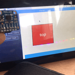
As the accelerometer is moved, the object on the screen moves along with it. This is done by feeding accelerometer data to the app via MQTT, and then applying the appropriate CSS transforms to show motion.
I was originally planning on showing pitch and roll with gauges (and I still think that, for the final product, that would be more useful), but stumbled into this while writing some debug scripts and thought it was a cool effect. Anyone know how to make a 3D CSS-only sailboat model?
Table of Contents
- Parts List
- Architecture
- Hooking up the Accelerometer
- Translating the Signal
- Publishing to MQTT
- Subscribing to MQTT in a React Component
- Visualizing Accelerometer Data with CSS
Parts List
- Adafruit ADXL335 Triple-axis Accelerometer
- MCP3008 Analog to Digital Converter
- Breadboard and Jumpers
- Raspberry Pi 3 B+
Architecture
Accelerometer -> MCP3008 -> Pi -> MQTT -> React App
Hooking up the Accelerometer
The Adafruit ADXL335 is a triple-axis accelerometer, meaning that it can detect tilt on the X (pitch), Y (roll), and Z (flip) axes. Typically you’d hear “pitch, roll, and yaw”, but yaw (rotation around the z axes) can’t be detected by an accelerometer like this one- instead the Z axes is used to let you know if the sensor is upside down, which can then be used to modify the math for pitch and roll. I’ve actually skipped that for now… if the boat is upside down there are bigger problems.
Most simple sensors send signals in one of two ways- digital or analog. Digital signals are boolean (true/false) depending on if voltage is present or not. Analog signals are more of a gradient- they’ll be anywhere from 0 volts to whatever the system voltage is (3.3v for the Pi 3 B+).
The Raspberry Pi’s GPIO pins don’t support analog signals out of the box, which is where the MCP3008 comes in. It is a small, relatively inexpensive, Analog to Digital Converter (ADC). It has 8 analog input pins on one side, and the other side’s pins are for power and to output as a signal that can be read by the Raspberry Pi’s SPI (Serial Peripheral Interface) bus.
Each of the 3 ADXL335 outputs goes to a channel on the MCP3008- order doesn’t really matter, but I did X on 0, Y on 1, and Z on 2.
Wiring Diagram/Picture of ADXL335 -> MCP3008 -> Pi
To fully understand how the MCP3008 converts from analog to digital, you need to dig into system clock speeds and polarities and a hundred other things- that’s all out of scope for this project, and fortunately someone already created mcp-spi-adc, a great NodeJS package for working with these things.
Using mcp-spi-adc, I wrote a script to continuously read the raw values and log them to the console:
1 | let interval = 1000; |
Example output:
1 | [ |
The script outputs voltages, which I then need to translate into pitch and roll angles.
Translating the Signal
By moving the accelerometer around, I observed that the lowest values were approximately 0.46, and the maximum were around 0.57. The accelerometers work by electrical resistance (lots of cool information in the ADXL335 Datasheet!) and aren’t perfect- so rather than signals between 0 and 1, we’re actually seeing a much smaller range.
Thinking back to geometry class, I remembered that I could use arcsine (the inverse of the sine function) to translate numbers between -1 and 1 into angles. In order to do that, I first had to ‘normalize’ the accelerometer readings by centering them around 0 and expanding the range. Then, I add some bounds to the normalized input (can’t arcsine if |x| > 1) just in case. My code looks like:
1 | let min = 0.4600; |
These are ‘magic numbers’ that might not work for every implementation- I suspect that the min/max values change based on many factors including temperature and humidity. In the future I’d like to write a calibration script that will calculate all of this after a few seconds of wiggling the sensor around- I think this is more or less how the iPhone tilt calibration works.
Once we’ve got readings between -1 and 1, we can run them through the arcsin function to get some angles! Math.asin() returns angles in radians, which I then translated into degrees using another JavaScript Math function.
1 | let output = Math.degrees(Math.asin(normalizedInput)); |
Publishing to MQTT
In my original design, I was publishing all of my telemetry data to the AWS IoT platform to do analysis. I’ll still do that, but I want to make sure that everything works well offline, so I decided to create a local MQTT broker using Mosquitto. This will allow any devices connected to the Raspberry Pi to
Installing Mosquitto wasn’t as simple as I had hoped. You can get it from a few different places, and it was tough to debug what was going on. I mostly relied on this article to figure out how to run the Mosquitto service and the NPM MQTT package.
By default, Mosquitto creates a listener on port 1883 using the MQTT protocol. I wanted to also add a websocket listener so that I can subscribe through front-end clients. You can set this up by adding a few lines to a configuration file that is created when installing Mosquitto, located at /etc/mosquitto/mosquitto.conf and restarting the service with .
1 | # ~/mosquitto.conf |
This adds some flexibility in how the MQTT broker can be interacted with- particularly important because the React MQTT library that I used in the next step only works through websockets.
Once Mosquitto was set up, I added a few lines to my script to publish the data to an MQTT topic.
1 | const client = new mosquitto.client('ws://localhost:9001'); |
I was then able to subscribe to the MQTT topic in the command line:
1 | mosquitto_sub -t sensor-data/clinometer |
So now that the data is flowing out to the MQTT broker, the next step is subscribing to it on our front-end. I’ll save that for next time!